Table of Contents
Fitting the Crankshaft Position Sensor
This applies to fitting the Kia Crankshaft Position sensor to a B2000, B2200, B2600i or Bongo Bell housing.
General notes before starting
Below is a guide to drill your bell housing for the Crankshaft Position Sensor. This approach utilizes the bell housing from a donor car, however the same principles can be applied to determine the measurements without the donor car (Step 3 outlines the difference in approach). The following steps used a KIA Sportage 2000 Fe3 and transmission (automatic or manual), and a B2200 manual transmission. It should also be noted that all my measurements are in metric (ie. millimeters on my micrometer). Please follow this process and take your own measurements, Different castings may well give you different measurements. It will only be as good as you make it. Tools: Sharpie, Vernier Caliper (should measure depths and lengths), 90 degree set square(for a straight edge) and a feeler gauge.
Step 1 - Attach Flywheel
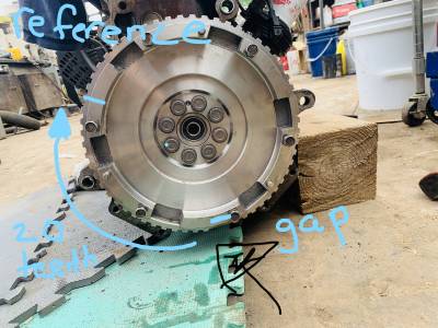
Remove the plate shield between the motor and the transmission bellhousing. Attach your new flywheel to the Fe3 with this plate removed (don't use lock tight as you will likely be removing). This will allow you to see the flywheel while the transmission is attached to the motor. Make sure you line up with the dowel. (For automatic donor cars - If your Fe3 donor car was an automatic, and you are converting to a B2200 manual transmission ensure you remove the doughnut spacers which were inserted behind the automatic Kia Sportage Flywheel. From my understanding the spacers are to make up for difference in flywheel widths. It should be noted that the flywheel is a 60:2 Trigger wheel. From my understanding this means there is 58 teeth, and a gap of 2 missing teeth.
Step 2 - Find Top Dead Center
Set the motor to Top Dead Center on piston 1 combustion stroke by aligning the indicators on the crankshaft and camshaft pulleys. Once indicators were aligned, i inserted a micrometer with a depth reader down the piston 1 spark plug hole to find the exact point of Top Dead Center. I recommend performing this step between every measurement step below to ensure that you are consistently performing actions while at Top Dead Center. If you need assistance finding TDC, search 'Kia Sportage 2000 Top Dead Center' and there will be lots of helpful resources. At top dead center the 2 teeth gap should be near the bottom of the motor.
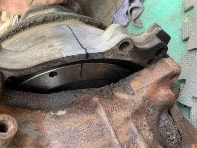
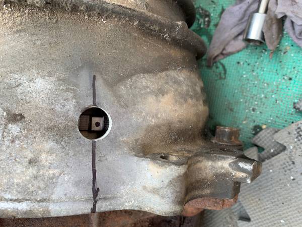
Step 3 - Identifying Reference Tooth
I attached the bell housing from my donor car to the Fe3 motor(ie. Kia Sportage Transmission bell housing - i actually unbolted the bell housing from an automatic transmission to make it more portable). If you haven't already, remove the crankshaft position sensor from the bell housing. Which ever tooth you see through the crankshaft position sensor mount hole while the bell housing is attached to the Fe3 will become your “reference tooth”. Mark this tooth (i used a dot with a black sharpie, and brake cleaner to remove once all steps are complete). If you do not have the Bell Housing, so long as your set the engine to TDC, you can count the number of teeth from the 2 teeth gap in the flywheel. I noted the reference tooth is the 20th tooth from the gap counting clockwise. The reference tooth should fall on the exhaust side of the motor, slightly above the lower transmission mounting bolts.
Step 4 - Marking the Plane
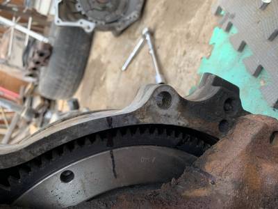
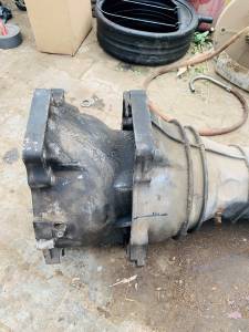
Next i removed the bell housing of the donor car, and attached the B2200 transmission (the bell housing doesn't unbolt from the transmission). Using the marked tooth as reference, i placed a marking on my bell housing the represent the plane which the Crankshaft Position Sensor hole will be drilled. For a sanity check, you can then place the B2200 and Kia bell housing side by side to confirm that the marked plane on the B2200 is in the same location as the Kia Sportage housing.
Step 5 - Determine Where to Drill on the Measured Plane:
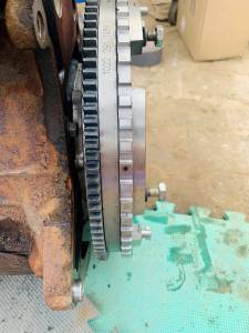
The purpose of this next step is to determine where on our marked plane that a drilled whole will be perfectly centered over the marked referenced tooth. It should be noted that this measurement can be taken in a variety of ways. The general idea is to measure the gap between the engine face plate, and the flywheel sensor teeth, and transpose this length onto your marked plane. You need to be sure you account for the steel plate which rests behind the flywheel, between engine faceplate and the transmission bellhousing. My method and measurements are as follows (please don't rely on my measurements, please calculate your own:
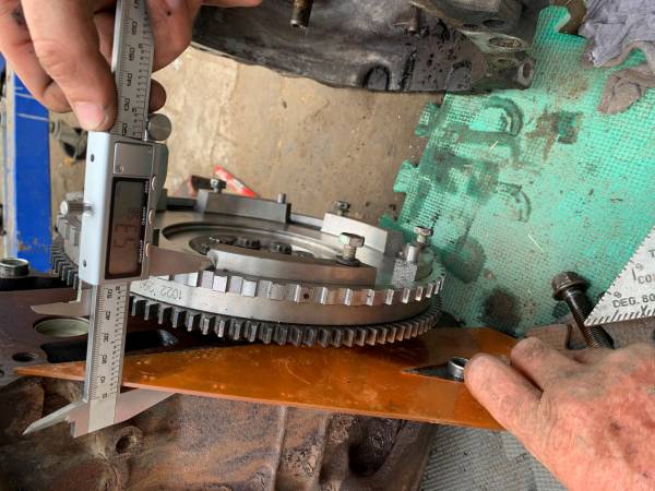
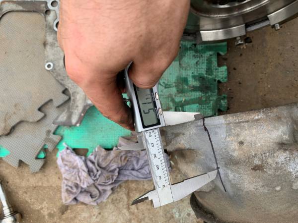
- Measure the distance between the engine face plate and flywheel teeth (far side). I measured to be 53.58mm.
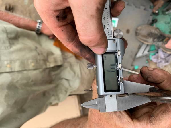
- Measure the thickness of the steel plate between transmission bell housing and engine face plate. I measured to be 1.88mm.
- Mark the calculated difference on the plane. I calculated gap to far side of the flywheel teeth from the front of the bell housing to be 51.7mm (53.58-1.88).
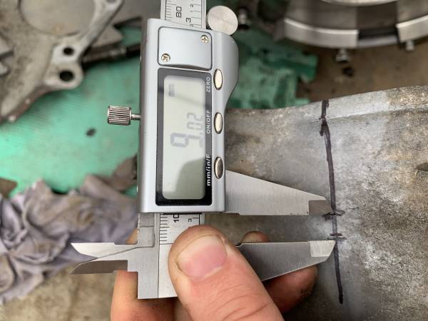
- Measure the thickness of the flywheel teeth. I measured to be 9.16mm.
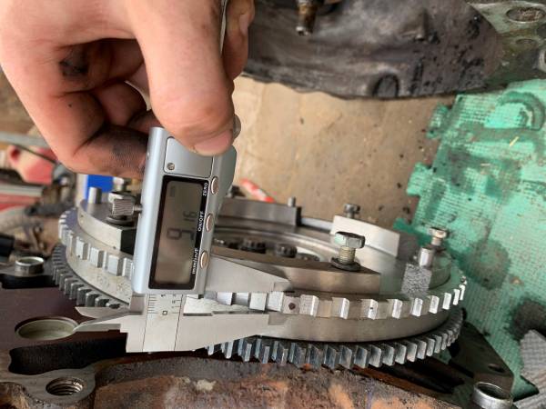
- Mark the difference between your previous mark, subtracting the width of the flywheel teeth. I removed 9mm from my previous measurement of 51.7mm The 2 marks on the plane will indicate where the flywheel teeth are. Your objective is to drill in the middle of the 2 marks.
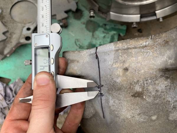
- Removed or add 1/2 of the flywheel teeth width to either mark to determine the middle of the reference tooth. I removed 4.5mm from my previous measurement of 51.7mm.
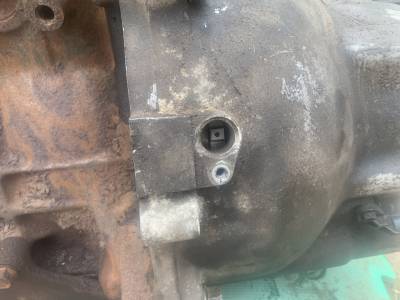
- Drill a hole in your marked location. I recommend starting with a small drill bit, such as a 9/64 and increasing in size slowly. Use a micrometer to measure size width of your crankshaft position sensor to determine a drill bit which will create a snug fit. Anything close to a 11/16 drill bit will be your final size. Snug is best, but if it is a little sloppy it isn't the end of the world. JB Weld will solve that issue.

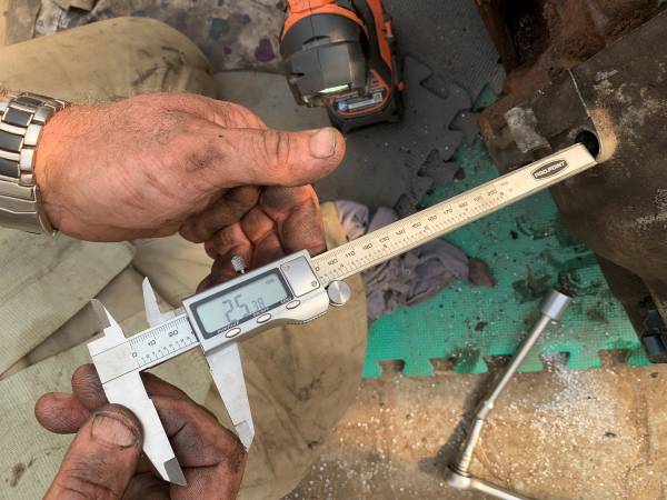
Step 6 - Depth of the Sensor
Next we need to determine the appropriate depth of the sensor. Attach the donor bell housing and install the crankshaft position sensor. Using a feeler gauge you can get an estimate for the gap required for your final product. Please note it is hard to get an accurate measure with the feeler gauge as it is a very awkward space to access. As such for a more accurate measurement, i then removed the bell-housing and flywheel to reattach the steel shield plate between the transmission bell housing and the engine plate. Next re-install the donor bell housing without the crankshaft position sensor. Using a depth feature on the micrometer, you can measure the depth from the top lip the crankshaft position sensor mount to the top of the reference tooth. My average measurement came out to a depth of approximately 25.3mm. This is the depth that you need to recreate on your transmission.
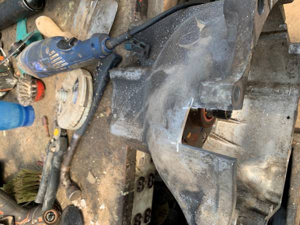
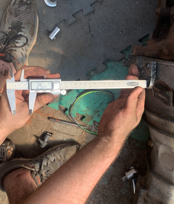
Step 7 - Creating the Senor Mount
The final step is to recreate the sensor mount to have the same depth as factory. There are a variety of creative ways to recreate the mount and depth whether it be using washers as spacers, cutting off the stock mount, or somewhere in between. I will let you decide what is best for you dependent on your skills, and available resources. I chose to cut the stock mount off the Kia Sportage Donor transmission, and attach it to my B2200 transmission through tapping holes for bolts, and JB Weld as it seemed to be the simplest method. If you choose this method, I warn you take your time to slowly grind down the mount to fit perfectly once you have cut it off. Simply cut the mount off the donor transmission. Then slowly start to grind it down until it lays flush on the B2200 transmission, and results in a depth equal to that of which you measured. The more time and patience the better it will fit. I went too quickly and this resulted in me needing to use a washer as a spacer. The idea is once the mount is secured, you recreate the same depth measured from the same spot. My final depth was just of 25mm. Preferably the gap is no more then 1.2mm.
Sources and Credit
Written and Photographed by @56josh10
Edited and Published by @Lynxdragon
